Privacy statement: Your privacy is very important to Us. Our company promises not to disclose your personal information to any external company with out your explicit permission.
Key words: metal products, spinning processing, Delta CNC, servo
1 Introduction
In the field of metal processing engineering, spinning is a new technology for chipless forming of metal products. Spinning process utilizes the ductility of metal, and combines the characteristics of forging, extrusion, drawing, bending, ring rolling, cross rolling and rolling to achieve a high-quality and efficient metal forming process with no cutting. Strong spinning has developed rapidly since the 1950s. The molding technology has the advantages of good deformation conditions, good product performance, small dimensional tolerance, high material utilization rate, wide product range, and processable seamless hollow rotary body parts. It has demonstrated its advancement, practicality and economy in the industrial sectors of advanced industrial countries. The successful application of spinning technology and equipment not only promotes the development of cutting-edge technologies such as aviation, rockets, missiles and satellites, but also in the industrial sectors such as conventional weapons, chemicals, metallurgy, machinery manufacturing, electronics and light industry and civilian use. Large-scale metal processing technology equipment and products. Spinning as a new technology has developed in parallel with traditional processes and has formed a new field of modern metal pressure processing.
2 CNC spinning machine design
The process equipment for spin forming is a spinning machine. The processing of thick-walled metal cylindrical parts, including refractory metals, non-ferrous metals, stainless steels, etc., by force spinning into thin-walled pipes of various sizes or by special-shaped spinning into shaped hollow rotary parts by means of a spinning processing device. Spin forming is to clamp the blank on the core, and the spinning core drives the core and the blank to rotate at a high speed. At the same time, the pressure and the feed motion of the roller are used to locally deform the blank, and finally the axisymmetric part is obtained. The spinning mold is simple and localized, and large parts can be processed by equipment with small power and tonnage, and it is mostly used for small and complex shapes. The principle of the spinning machine is that when the workpiece rotates at a high speed, the workpiece is pressed by a certain path through a strong external force, and the material is repeatedly pressed by the roller to make it from point to line, and the line to the surface eventually causes the workpiece to be thermally deformed. The shape you need. Depending on the required pressing force, the small spinning machine can drive the screw to generate pressure through the servo motor. Some large-scale powerful spinning machines need to be squeezed by hydraulic means.
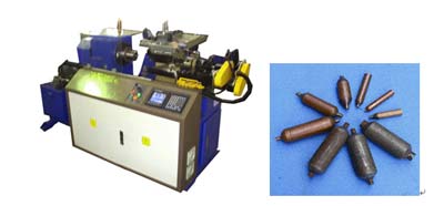
This example introduces a steel pipe spinning machine, which is mainly used to reduce the diameter of the pipe head, and the produced parts are used in some refrigeration industries. The electrical control system adopts Zhongda Dentsu PUTNC-H4-2 numerical control system + two sets of Delta servo system. The picture of CNC spinning machine is shown in Figure 1. See Figure 2 for the molded product of steel tube spinning machine.

Figure 1 CNC spinning machine Figure 2 Rotary compression tube molding products
2.1 Spinning machine structure principle
Spindle: Drives the workpiece to rotate. Small wheel: The XY axis table drives the small wheel to squeeze the workpiece according to a certain path. Turning tool: After the spinning is completed, the end face of the workpiece is properly trimmed with the turning tool. Feeding mechanism: See the following actions for related actions.
2.2 CNC system design
The logic action is controlled by the M code in parentheses. The order of action of loading and unloading can be referred to the attached machining program.
(1) Feeding in/out (M06/M07): The workpiece is sent to a position where the material can be pushed into the chuck, and the feeding frame cannot be stopped at this position during the processing.
(2) Blowing on/off (M08/M09): Cooling the workpiece by blowing air.
(3) Chuck clamping/releasing (M10/M11): Clamp the workpiece for processing.
(4) Pushing in/out (M12/M13): The workpiece is fed into the spindle chuck by a cylinder.
(5) Tailstock tight/loose (M14/M15): After the mandrel is in place, the mandrel must be clamped to prevent the mandrel from being squeezed out during processing.
(6) Unloading advance/retract (M16/M17): The workpiece is pushed out from the chuck.
(7) Feeding material 1 in/out (M18/M19): Matching material 1 and material 2 are combined to ensure that only one material is used at a time.
(8) Feeding material 2 in/out (M20/M21): Matching material 1 and material 2 are combined to ensure that only one material is used at a time.
(9) Mandrel advance/retract (M79/M78): There is a requirement for the inner hole size when the workpiece is processed, and the spinning is not allowed to ensure the inner hole size on the outer surface. Therefore, it is necessary to put the mandrel into the workpiece during processing to ensure the inside. Hole size.
(10) Spinning automation: The XY axis table drives the small wheel to squeeze the workpiece according to a certain path. Different workpieces have different spinning paths.
Next page
E-mel kepada pembekal ini

Privacy statement: Your privacy is very important to Us. Our company promises not to disclose your personal information to any external company with out your explicit permission.

Fill in more information so that we can get in touch with you faster
Privacy statement: Your privacy is very important to Us. Our company promises not to disclose your personal information to any external company with out your explicit permission.